

After visiting the Smithsonian National Museum of Natural History and seeing the case with minerals that emit radiation, getting a geiger counter seemed like a good tool to have. So after studying various models I bought a Monitor 4 kit from GiegerCounters.com. After receiving the kit and reading the through assembly instructions, I took the time to gather my tools. Having never worked with a Geiger-Müller tube before I was apprehensive toward handling it to the point of considering using latex gloves. After seeing the tube casing, it seemed okay to handle [make sure no contact with the mica window].


Next the output connector is soldered on and the speaker.
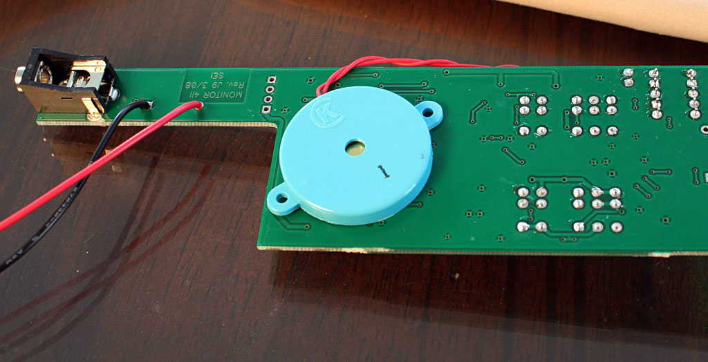

A diode to mount the meter to is installed along with a a foam piece for circuit board support.


Here is a close up of the Geiger-Müller tube probably made in Tennessee. I did not take pictures of this assemble step because I was concentrating on not breaking this tube.

After testing the circuit board, the tube, speaker, and battery clip are placed in the bottom half of the case. The top half then fits over that to complete the case. Five screws lock it all together. I still have to put conformal liquid on part of the circuit board to seal the high-voltage components from moisture. Also once I have my digital meters calibrated I will make some adjustments to the detector.

Fortunately, I found no common items around the house that generate radiation (checked the smoke detectors, granite rock, New Albany shale, potassium chloride salt substitute).
The detector has two sets of switches. Switch 1 has an off, on, on with speaker, and battery test setting. Switch 2 has a 1x, 10x, and 100x setting. So the analog meter can display 0-50000 CPM. The user outputs are a little red LED, an analog meter, and a speaker.

Later, I checked the detector on a Meta-autunite specimen that generated about 300 CPM. It was good to see it working!

Setting the detector to 100x it measured about 8000 CPM on a Torbernite mineral specimen.

All and all, an interesting experience assembling and testing the Monitor 4. I believe the tool will be useful in finding Uraninite specimens.
Learn more about Geiger Counters with Professor Bob Burk (Carleton University - Ottawa, Canada) from this YouTube video: